
PSTN Analog Lines Fail-Over for IP-PBX
Suits any Asterisk® based IP-PBX that uses Xorcom’s XPP™ technology Get a QuoteAll Xorcom Products

Simple PSTN Analog Lines Fail-Over Solution for IP-PBX
Suits any Asterisk® based IP-PBX that uses Xorcom’s XPP™ technology
P/N XR0128
In case of power outage or an Asterisk malfunction, up to six analog PSTN lines are routed directly to predetermined analog extensions using this analog lines fail-over module.
Keep IP-PBX Phone Lines Working Even in the Absence of Electricity
While the benefits of an IP-PBX over a traditional PSTN-only phone system are indisputable, there is still one area where PSTN has the upper hand: during power failure the old-style telephone system continues to operate. Unlike an IP-PBX, it is not dependent on electricity to support placement and reception of calls. Therefore, for the benefit of those who want the advantages of an IP-PBX with the resiliency of PSTN PBX during power outages, Xorcom has designed a product for Asterisk®-based IP-PBX configurations that will allow automated fail-over of FXO lines to pre-defined FXS extensions in case of power failure.
This functionality is comparable to Power Failed Transfer (PFT), which is used extensively in hospitality and other installations that rely heavily on large numbers of analog telephones. The simple addition of Xorcom’s analog lines fail-over solution to the IP-PBX will allow analog extensions to continue to function directly via PSTN lines, even when disaster strikes! The solution is based on the award-winning Astribank, a USB-connected telephony interface device designed specifically for Asterisk-based IP-PBX.
Analog Lines Fail-over Available in Two Formats
The Complete Solution
The Analog Lines Fail-over option can be purchased as a complete solution, based on the Astribank P/N XR0004, which contains 8 FXS ports and 8 FXO ports, as well as Input/Output ports, in addition to the special connectivity module required for the fail-over solution. Customers who want this option should purchase P/N XR0128.
The Add-on Solution
Under certain conditions, the fail-over solution can be purchased as an add-on for specific Xorcom Astribank and IP-PBX models. Please contact your Xorcom representative for details.
Components of the Analog Lines Fail-Over Solution
The Analog Lines Fail-over solution is supplied with the following components:
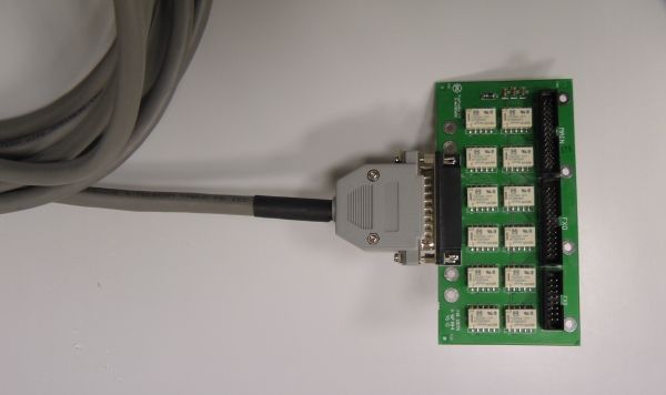
- a dedicated connectivity module
- flat cables to connect the connectivity module to the main board
- a 15 foot cable with DB 25 connector*
The connectivity module attaches to the system’s existing main board, FXO module and FXS module. The cable is connected via a standard DB25 connector placed on the Astribank / IP-PBX rear panel.
* This cable is installed in the Telecom Connection Option (TCO) add-on (P/N XR0034) space, so it cannot co-exist with it.
Installed Analog Lines Fail-over Components
Analog lines fail-over installation diagram.
How Analog Lines Fail-over Solution Works
During installation, the installer designates up to six extensions as emergency / backup lines. These extensions correspond to the first six physical ports in the FXS module. In case of a power outage or PBX malfunction, the PSTN lines will be physically connected to the assigned analog extensions, automatically. A direct PSTN dial tone will be available for each of the designated emergency phones, and the PSTN can be accessed directly. Incoming calls will ring the assigned extensions (one extension for each line).
The six supported FXS extensions and PSTN analog lines are connected directly to the connection block on the rear panel. The front panel RJ11 connectors are not used (although the LED indicators will function normally).
How to Attach the External Cable to the Analog Lines Fail-over Module
Below is the FXS-FXO switch PB0690 DB25 wiring diagram:
| Color A | Color B | Pin A | Pin B | Line | Phone |
|---|---|---|---|---|---|
| Gray-Brown | White | 1 | 14 | 1 | |
| Orange-Red | White | 2 | 15 | 1 | |
| Green-Black | White | 3 | 16 | 2 | |
| Brown | White | 4 | 17 | 2 | |
| Green | White | 5 | 18 | 3 | |
| Orange-Green | White | 6 | 19 | 3 | |
| White-Green | White | 7 | 20 | 4 | |
| Gray | White | 8 | 21 | 4 | |
| Blue | White | 9 | 22 | 5 | |
| Orange | White | 10 | 23 | 5 | |
| Green-Blue | White | 11 | 24 | 6 | |
| Orange-Blue | White | 12 | 25 | 6 |